
A regular phone call feels instantaneous: you speak a word, and fractions of a second later a colleague on another continent hears your voice. In legacy TDM telecommunication networks, every call was allocated a dedicated, guaranteed physical circuit operating at a constant 64 kbps. In IP packet networks, there are no reserved circuits: continuous acoustic waveforms are sliced into discrete time chunks, encapsulated into independent UDP datagrams, and forwarded across routers using statistical multiplexing. In this lesson, we trace every step of this engineering pipeline — from air pressure waves vibrating at the microphone to the analog acoustic reconstruction at the loudspeaker.
Goal and prerequisites
After this lesson, you will be able to:
- trace the complete end-to-end VoIP transmission pipeline from microphone to loudspeaker;
- explain the fundamental physical and architectural differences between IP telephony and legacy TDM circuits;
- calculate essential voice digitization and packetization parameters (sampling rate, frame duration, packet cadence);
- isolate faulty functional blocks when troubleshooting latency, speech clipping, or audio distortion.
What you need to know beforehand: telbasics 12–16 (sound, frequency spectrum, noise), telbasics 21–25 (sampling, quantization, 64 kbps PCM), ipnet 2–3 (OSI model, encapsulation, Ethernet), and ipnet 35 (UDP protocol).
A real-life task
A network engineer is upgrading an enterprise telephony environment: replacing an aging E1 ISDN PRI digital trunk with a modern cloud PBX over a SIP trunk across corporate IP infrastructure. During initial testing, employees report an odd anomaly: some calls sound pristine, while others suffer from chopped syllables, metallic clicking, or awkward speaker collisions. Under the legacy E1 circuit, such symptoms were physically impossible. To resolve the issue and tune equipment properly, the engineer must understand exactly how digitized voice flows through hardware and software blocks, and where vulnerabilities emerge in a statistically multiplexed network.
Voice Path Anatomy: From Acoustic Wave to IP Packet
Human speech consists of mechanical air pressure vibrations with an effective telecommunication frequency spectrum ranging from 300 to 3400 Hz. To transmit this acoustic signal over a digital packet network, the transmitter performs a sequence of hardware and software transformations.
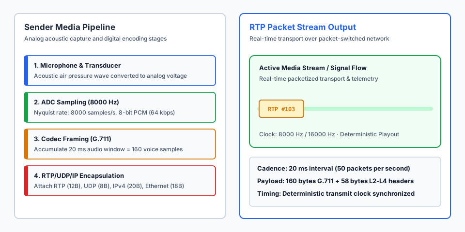
- Microphone (acoustic transducer): converts mechanical air pressure vibrations into a continuous analog electrical voltage signal.
- Analog-to-Digital Converter (ADC): samples the analog voltage according to the Nyquist-Shannon theorem at 8000 Hz (8 kHz). Every 125 microseconds, an instantaneous amplitude sample is captured and quantized into a digital value.
- Voice Codec (DSP/Encoder): the digitized samples are encoded according to a standardized codec algorithm (such as uncompressed 64 kbps G.711 A-law/μ-law, or compressed formats like Opus/G.729).
- Voice Packetizer: accumulates speech samples over a predetermined packetization window (standard default
ptime = 20 ms, corresponding to 160 audio samples at 8 kHz) to assemble the media payload. - RTP/UDP/IP Encapsulation: the payload is encapsulated with a 12-byte RTP header (carrying sequence numbers and timestamping), an 8-byte UDP header, a 20-byte IPv4 header, and an 18-byte Ethernet L2 frame header.
Worked example: calculating baseline voice stream metrics
Let us calculate the packetization parameters for an uncompressed G.711 stream at a standard 20 ms packetization interval:
Sampling rate (fs):        8000 Hz (8000 samples/sec)
Sample interval:           1 / 8000 = 0.000125 s = 125 us
Bit depth:                 8 bits (1 byte per sample)
Audio bitrate:             8000 * 8 = 64000 bps (64 kbps)
Packetization time:        ptime = 20 ms = 0.020 s
Audio samples per packet:  8000 * 0.020 = 160 samples
Voice payload size:        160 samples * 1 byte = 160 bytes
Packet rate (cadence):     1000 ms / 20 ms = 50 packets/sec (pps)
Every 20 milliseconds, the voice gateway timer triggers the transmission of a single 160-byte payload packet into the local network stack.
TDM Circuits vs. IP Networks: The Paradigm Shift
The legacy Public Switched Telephone Network (PSTN / TDM) was engineered around circuit switching principles, whereas IP telephony relies entirely on statistical multiplexing.
| Metric | Traditional TDM Telephony (E1 / PCM) | Packet VoIP Telephony (IP / Ethernet) |
|---|---|---|
| Resource Allocation | Dedicated fixed 64 kbps timeslot | Statistical sharing of common bandwidth |
| Conversational Pauses | Timeslot occupied transmitting silence | Pauses release bandwidth for other network traffic |
| Cabling Infrastructure | Separate telephone wiring and punch blocks | Unified converged Ethernet corporate LAN/WAN |
| Transmission Impairments | Purely physical wire attenuation | Router queuing delays, jitter, UDP packet loss |
Migrating to VoIP allows organizations to unify voice, video, and data over existing enterprise Ethernet switches, eliminating dedicated telephone wiring and costly proprietary E1 interface modules.
The Receiver Playout Pipeline: Reconstructing Continuous Audio
In an IP network, packets travel independently and experience variable network queuing delays (jitter). To deliver natural, intelligible speech, the receiving endpoint must reconstruct a strictly isochronous playout cadence.
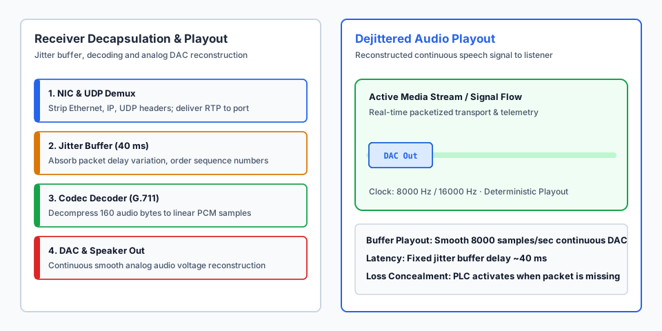
IP Packet Arrival (variable delays: 18ms, 25ms, 12ms, 31ms)
  │
  ▼
[Dejitter Buffer (reorders packets, absorbs delay variance)]
  │ steady 20ms playout
  ▼
[Audio Decoder (G.711 / Opus: decompresses payload)]
  │ 8000 samples/sec PCM
  ▼
[Digital-to-Analog Converter (DAC) & Smoothing Filter]
  │ continuous analog voltage
  ▼
[Loudspeaker / Headset (acoustic pressure wave)]- Network Interface & Decapsulation: the NIC receives Ethernet frames, strips IP and UDP headers, and routes RTP datagrams to the application media port.
- Dejitter Buffer: buffers arriving packets for 30–50 ms, sorts them by RTP sequence numbers, and compensates for packet arrival variance.
- Audio Decoder: extracts the 160-byte audio payload and recovers digital voice samples. If a packet is lost, Packet Loss Concealment (PLC) synthesizes replacement audio.
- Digital-to-Analog Converter (DAC): converts numeric digital samples back into continuous analog electrical voltages.
- Loudspeaker (acoustic emitter): the speaker diaphragm vibrates the surrounding air, recreating the original acoustic sound wave for the listener's ear.
What can go wrong and how to find it
| Symptom | Likely cause | What to check |
|---|---|---|
| One-way audio (complete silence in one direction) | Firewall or NAT device blocking incoming UDP RTP media ports | Inspect SDP media IP/ports in SIP signalling and verify NAT tables |
| Robotic metallic sound and speech clicks | Jitter buffer underrun caused by sudden network queuing spikes | Review jitter and packet loss statistics in RTCP gateway reports |
| Callers constantly interrupt and talk over each other | Total mouth-to-ear latency exceeds the 150–200 ms threshold | Measure round-trip ping time (RTT) and jitter buffer depth |
| Caller hears an echo of their own voice | Acoustic coupling between speaker and microphone at far end | Verify that Acoustic Echo Cancellation (AEC) is active at far end |
⚠️ The most common beginner VoIP troubleshooting mistake is analyzing only SIP signalling logs. SIP signalling only negotiates IP addresses and media ports (SDP); the voice media itself travels over a completely independent UDP/RTP stream. Always verify that RTP UDP packets actually pass through intermediate firewalls.
Practice
- Predict. If the voice sampling rate is increased from 8 kHz to 16 kHz while keeping 8-bit resolution, how will the 20 ms payload size change?
- Verify. Calculate the number of samples in 20 ms at 16 kHz:
16000 * 0.020 = 320samples. The payload size doubles exactly to 320 bytes. - Explain. Why does packet telephony employ UDP for real-time voice transport rather than reliable, acknowledged TCP?
- Modify. Calculate how many packets per second (pps) are transmitted if the packetization interval is lowered from 20 ms to 10 ms.
- Do it yourself (starred ⭐). A voice gateway concurrently handles 30 calls using G.711 (160-byte payload, total 218-byte Ethernet frame). Calculate the aggregate packet rate (pps) and the total bandwidth consumption in kbps on the switch uplink.
Self-check
Question 1. In what chronological sequence does a voice signal traverse hardware and software stages on the transmitting IP phone?
Analysis. Acoustic air pressure vibrations strike the microphone transducer to generate analog electrical voltage. The ADC samples the analog signal 8000 times per second. The codec encodes digital audio samples. The packetizer accumulates 160 samples over 20 ms. The encapsulation engine attaches RTP, UDP, IP, and Ethernet headers.
Question 2. How many audio samples and payload bytes are contained in a single G.711 packet when configured for 10 ms and 30 ms ptime?
Analysis.
ptime = 10 ms:
  Samples = 8000 samples/s * 0.010 s = 80 samples
  Payload = 80 samples * 1 byte = 80 bytes
  Packet rate = 1000 / 10 = 100 packets/sec

ptime = 30 ms:
  Samples = 8000 samples/s * 0.030 s = 240 samples
  Payload = 240 samples * 1 byte = 240 bytes
  Packet rate = 1000 / 30 = 33.33 packets/sec
Answers to practice: 1 — the payload size doubles to 320 bytes. 3 — retransmitting a lost TCP packet incurs hundreds of milliseconds of delay; by the time an acknowledged retransmission arrives, the conversation has moved forward and the late packet is useless. 4 — 1000 / 10 = 100 pps instead of 50 pps. 5 — aggregate packet rate: 30 * 50 = 1500 pps; aggregate bandwidth: 1500 * 218 * 8 / 1000 = 2616 kbps (~2.62 Mbps).
Review and the criterion for moving on
Move on to the next lesson if you can without assistance:
- enumerate all stages of the voice transmission and playout pipeline from microphone to loudspeaker;
- explain the mathematical relationship connecting an 8000 Hz sampling rate, 20 ms ptime, and a 160-byte payload;
- state why TCP retransmission delays make it fundamentally unsuitable for interactive voice conversations.
Standards and sources
- ITU-T Recommendation G.711 (1988) — Pulse code modulation (PCM) of voice frequencies.
- IETF RFC 3550 — RTP: A Transport Protocol for Real-Time Applications.
- IETF RFC 768 — User Datagram Protocol (UDP).
- ITU-T Recommendation G.100 / P.10 — Vocabulary for performance and quality of service.
