
For decades, telephony and computer networks evolved along two separate tracks: voice was carried over dedicated TDM circuits with a rigid 64 kbps allocation, while internet traffic and network management used completely separate cables and routers. Today, telecom operators are decommissioning legacy circuit-switched exchanges and migrating all voice and signalling traffic onto a unified All-IP packet network. In this lesson, we examine why parallel infrastructures became uneconomical, how statistical multiplexing works, and the three major engineering challenges encountered when transporting voice over IP networks.
Goal and prerequisites
After this lesson you will be able to:
- explain why telecom operators abandoned separate TDM networks and converged onto All-IP;
- calculate bandwidth efficiency under statistical packet multiplexing compared to rigid E1 (64 kbps) channels;
- describe the three critical challenges of packet voice: latency, QoS prioritization, and plane separation;
- classify network traffic into planes: signalling (Control Plane), media (User Plane), and administration (Management Plane).
What you need to know beforehand: the telbasics course (Section 5: circuit switching vs packet switching, PCM 64 kbps digital voice, E1 frame structure, latency, and jitter).
A real-life task
A regional telecom operator serves 100,000 fixed-line telephone subscribers while operating a municipal data network. Historically, the central office maintained two completely independent equipment rooms: one humming with digital telephone exchanges connected to heavy bundles of copper E1 cables and SDH optical multiplexers, and the second housing IP routers providing internet access.
When management decided to launch video calling and wideband High-Definition voice (HD Voice), the legacy TDM exchange proved incapable of allocating channels wider than 64 kbps without an expensive overhaul of its switching fabric. Maintaining two separate networks, duplicate 24/7 technical support teams, and redundant diesel generators resulted in unsustainable operating expenses (OPEX). Engineers were tasked with converging both networks onto a single All-IP packet infrastructure.
Two separate networks: the TDM legacy
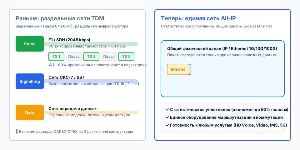
In traditional telephony, voice transmission was based on circuit switching using Time Division Multiplexing (TDM). When an off-hook condition and dialling occurred, the exchange allocated a dedicated physical 64 kbps time slot end-to-end between the two telephones. That time slot remained occupied during every millisecond of the call, whether the subscriber was speaking or silent.
TDM E1 Stream (2048 kbps):
[TS 0: Sync] [TS 1: Voice A] [TS 2: Voice B] ... [TS 16: SS7 Signalling] ... [TS 31: Voice]
Each time slot = exactly 8 bits every 125 microseconds (64 kbps).
This model carries an inherent inefficiency: in an actual phone conversation, people speak alternately, pause, and listen to the other party. Studies demonstrate that the voice activity factor is approximately 0.4 (40%). This means that 60% of the time, the expensive digital 64 kbps circuit transmits pure silence.
Furthermore, to coordinate call establishment, operators built an independent Common Channel Signalling network (SS7 / C7) requiring specialized signalling gateways and dedicated physical links. Connecting customer internet required yet a third, independent network.
The idea of a converged packet network (All-IP)
The All-IP paradigm consolidates all telecommunications services into a single universal packet transport built on IP and Ethernet protocols. Voice, video, call setup signalling, internet traffic, and network element management are packaged into standard IP packets and carried over shared high-speed optical links (1 Gbps, 10 Gbps, 100 Gbps).
Instead of fixed time slots, packet networks employ statistical multiplexing: a packet is generated and transmitted onto the wire only when the microphone detects speech or when an endpoint requests data. During pauses, packet generation ceases, and the unused bandwidth is immediately made available to other calls or file downloads.
| Parameter | TDM Network (Legacy) | All-IP Network (Modern) |
|---|---|---|
| Switching Method | Circuit Switching (TDM) | Packet Switching (IP) |
| Bandwidth Allocation | Rigidly fixed (64 kbps) | Dynamic on demand |
| Bandwidth Efficiency | Low (idle during pauses ~60%) | High (statistical multiplexing) |
| Signalling | Dedicated SS7 network | Packet protocols on shared link |
| New Services | Difficult to deploy (64k limit) | Seamless (HD Voice, video, IMS, 5G) |
| Infrastructure | Two or three separate networks | Single converged network |
Worked example: E1 link utilisation vs All-IP
Let us compare the bandwidth required to support 30 concurrent voice sessions across a traditional E1 link versus a converged IP network.
1. Circuit Switching (TDM E1):
   Voice channels = 30 voice time slots × 64 kbps = 1920 kbps
   Framing time slots (TS 0 synchronization + TS 16 signalling) = 2 × 64 = 128 kbps
   Total constant link bandwidth = 2048 kbps (always 100% occupied).

2. Statistical Packet Multiplexing (All-IP):
   Voice Activity Factor k = 0.4.
   Active speech payload for 30 sessions: 30 × 64 kbps × 0.4 = 768 kbps.
   Packet header overhead (IP/UDP/RTP ~20%): 768 × 1.20 = 921.6 kbps.
   Bandwidth savings: 2048 − 921.6 = 1126.4 kbps (over 55% of the link capacity freed).
In an All-IP network, this freed capacity can immediately serve internet traffic or support 35 additional concurrent telephone users without installing new physical cables.
The three main challenges of All-IP
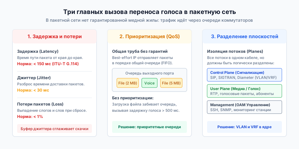
Abandoning dedicated physical circuits provides great agility and cost savings, but introduces three major engineering challenges that did not exist in TDM networks.
1. Delay, jitter, and packet loss
In TDM networks, propagation delay is strictly constant, governed by the speed of light in copper or fiber. In IP networks, packets travel through routers and switches, traversing intermediate buffers (queues).
- Delay (Latency): one-way mouthpiece-to-earpiece latency must not exceed
150 ms(ITU-T Recommendation G.114). If delay exceeds 250–300 ms, speakers begin talking over one another, rendering interactive conversation frustrating. - Jitter (Delay Variation): fluctuations in packet arrival times. Because queue lengths vary dynamically, packets from the same dialogue arrive at irregular intervals (one after 20 ms, the next after 45 ms). A jitter buffer is installed at the receiver to smooth playback.
- Packet Loss: when switch buffers fill up, excess packets are discarded. Losing more than
1%of packets produces audible gaps, clicks, and metallic distortion.
2. Traffic prioritization (QoS)
Standard IP functions on a best-effort basis: switches forward packets in simple FIFO (First In, First Out) order. If a user starts downloading a large software archive, the port queue fills with 1500-byte packets. Compact voice packets (160–200 bytes) are delayed behind the large file, ballooning latency to hundreds of milliseconds.
To resolve this, All-IP networks implement Quality of Service (QoS) mechanisms: voice packets receive priority marking and skip ahead of standard data queues.
3. Plane separation
Carrying all communications over a single physical link introduces interference and security risks. If a broadcast storm or malicious traffic in the user segment overloads a switch CPU, the exchange will fail to process incoming call signals. To prevent this, traffic inside an All-IP network is segregated into three planes:
- Control Plane: signalling messages that establish and tear down calls (protocols such as SIP, SIGTRAN, and Diameter).
- User Plane: active conversational voice payloads and media streams (RTP protocol).
- Management Plane (OAM): administrative access to network elements (SSH, SNMP, telemetry).
Technologies such as VoIP, IMS (IP Multimedia Subsystem), LTE, and 5G are founded upon this converged All-IP architecture.
What can go wrong and how to find it
| Symptom | Probable cause | What to check |
|---|---|---|
| Robotic, metallic voice quality or dropped syllables | Excessive jitter; jitter buffer overflow or underflow | Measure delay variation (target < 30 ms) and interface packet drop counters |
| Voice stutters and lags whenever large file downloads begin | Missing or misconfigured QoS prioritization on edge routers | Inspect DSCP markings on voice packets and verify Priority Queue scheduling |
| Loss of central office management during peak calling hours | Signalling or user traffic flooding management ports (lack of isolation) | Verify VLAN separation and ensure the Management Plane is isolated from user traffic |
| Call connects normally but there is complete silence (no one-way audio) | User Plane packets blocked while Control Plane ports remain open | Check firewall policies: signalling port is open but dynamic RTP voice port range is filtered |
⚠️ A common misconception is that migrating to All-IP automatically resolves bandwidth issues. Without strict QoS queuing and plane separation, bursty bulk data traffic will choke real-time telephony.
Practice
- Predict. What happens to conversational voice quality if one-way network latency increases from 40 ms to 400 ms?
- Verify. Consult ITU-T Recommendation G.114: at what latency threshold is telephone conversation deemed unacceptable?
- Explain. Why is it impossible in a classic TDM E1 link to use idle pause time for data transfer, whereas an IP network does so automatically?
- Modify. Calculate the bandwidth consumed by 50 concurrent voice sessions under statistical multiplexing (k = 0.4, 64 kbps codec, 20% overhead) and compare it with the required number of E1 links.
- Do it yourself (with a star ⭐). A central office Gigabit Ethernet interface handles SIP signalling, RTP voice media, and a backup file server. Propose a traffic prioritization and isolation design that prevents nighttime backups from degrading calls.
Self-check
Question 1. Why does voice channel bandwidth utilization in a TDM network rarely exceed 40–50%?
Walkthrough. Human speech is interactive: one party speaks while the other listens. Furthermore, natural speech includes pauses between words. In TDM, a 64 kbps channel is continuously dedicated to the subscriber, sending idle filler bytes during pauses.
Question 2. To which network plane does call setup signalling exchange belong?
Walkthrough. Exchanging control messages to negotiate, route, and terminate calls belongs to the Control Plane. The actual stream of digitised voice samples belongs to the User Plane.
Answers to practice:
TDM 50 calls:    50 × 64 kbps = 3200 kbps → 2 × E1 = 4096 kbps
All-IP 50 calls: 50 × 64 kbps × 0.4 × 1.2 = 1536 kbps
Bandwidth savings: 4096 − 1536 = 2560 kbps (62.5%)- Conversation becomes unnatural: speakers constantly interrupt each other and experience awkward pauses waiting for replies.
- According to ITU-T G.114, latency below 150 ms is acceptable for high quality, 150–400 ms requires careful management, and latency above 400 ms is unacceptable for interactive speech.
- TDM uses synchronous multiplexing: time slots are rigidly tied to a fixed position in the frame every 125 microseconds. IP uses asynchronous (packet) multiplexing: packets are formed only when data exists.
- Active payload:
50 × 64 × 0.4 = 1280 kbps. With packet headers:1280 × 1.2 = 1536 kbps. TDM would require 2 full E1 links (2 × 2048 = 4096 kbps), since one E1 handles only 30 calls. - Allocate three VLANs: VLAN 10 (Control Plane, SIP), VLAN 20 (User Plane, RTP), and VLAN 30 (Data/Backup). Configure a Strict Priority Queue for VLAN 20, guaranteed bandwidth for VLAN 10, and best-effort scheduling for the backup traffic.
Review and the criterion for moving on
Move on to the next lesson if you can independently:
- state the primary reasons telecom operators migrated from TDM to All-IP;
- explain the difference between circuit switching and packet switching using a telephone call as an example;
- describe the three main challenges of packet voice (latency/jitter, QoS, and plane separation).
Standards and sources
- ITU-T Recommendation G.114: "One-way transmission time" (specifications for voice transmission latency).
- ITU-T Recommendation Y.1541: "Network performance objectives for IP-based services" (QoS classes for IP).
- 3GPP TS 22.228: "Service requirements for the Internet Protocol (IP) multimedia core network subsystem (IMS)".
- IETF RFC 3261: "SIP: Session Initiation Protocol".
