
Fourth-generation 4G LTE networks gave the world fast smartphone internet, video calls, and high-definition streaming. Yet by the late 2010s, operators and engineers hit three fundamental barriers that could not be overcome simply by installing more 4G base stations: a severe shortage of channel bandwidth in dense urban areas, an irreducible 15–30 ms latency floor, and an inability to serve hundreds of thousands of sensors per square kilometer. In this lesson, we examine the three architectural limits of 4G LTE, the target metrics of IMT-2020 (5G) defined in ITU-R M.2083 / M.2410, and a step-by-step engineering calculation showing how the fifth generation boosts sector capacity by more than 12× while compressing latency to a few milliseconds.
Goal and prerequisites
After this lesson, you will be able to:
- name and explain the three primary architectural limits of
4G LTEnetworks (the capacity ceiling, the latency floor, and the connection density limit); - spell out and define the three IMT-2020 service pillars: eMBB, URLLC, and mMTC;
- list the eight core target metrics of ITU-R M.2083 / M.2410 and 3GPP TR 38.913 compared against IMT-Advanced (
4G); - calculate sector capacity using
C_sector = B * eta_avgand the end-to-endRTTlatency budget for both4G LTEand5G NR; - determine from an engineering specification which
4Glimit a project hits and which5Gservice pillar solves it.
Prerequisites: course lte, lessons 1–5 (why LTE was created, the E-UTRAN + EPC architecture, eNodeB base stations and S-GW / P-GW gateways, channels up to 20 MHz, and the 1 ms subframe); course ipnet, lessons 1–5 (throughput, RTT latency, jitter, and packet loss).
A real-life task
In a single week, a mobile operator's lead radio engineer in a major metropolis receives three completely different requests from the commercial department:
- A 45,000-seat city stadium. During a football match, thousands of fans simultaneously stream live video and watch instant replays in
Full HD / 4K. Even withLTE-Advancedcarrier aggregation, each base station sector is constrained by20 MHzcarriers, and throughput per active spectator drops below0.25 Mbps— video freezes. - An automated automotive factory. The customer wants to remove wear-prone cables from 120 welding robots and automated guided vehicles (
AGV), replacing them with a cellular network. The safety controller requires a round-trip response time ofRTT <= 5 mswith99.999%reliability. Measurements in the factory's4G LTEcell show22 ms, causing the robots to trigger emergency stops. - Smart city utilities (Smart Metering & Grid). The municipality plans to connect
350,000water meters, gas meters, parking sensors, and street-lighting controllers per square kilometer of the city center, each running for10 yearson a single battery.
The question for this lesson: why does the same 4G LTE architecture stall on all three tasks, and what exact technical requirements did the International Telecommunication Union (ITU-R) build into the fifth-generation IMT-2020 (5G) standard?
Three Architectural Limits of 4G LTE
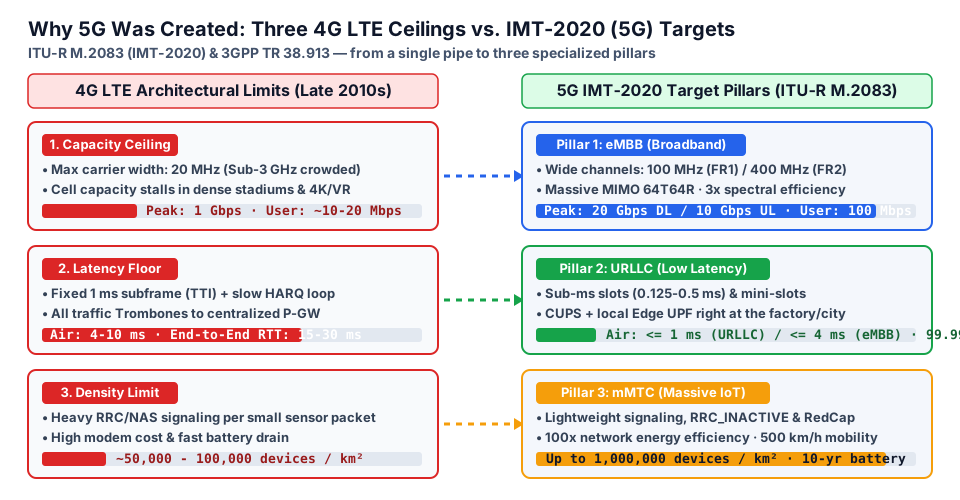
4G LTE (and later LTE-Advanced Pro in 3GPP Releases 8–14) was engineered around one primary goal: giving a human with a smartphone a universal IP data pipe. When operators tried to extend cellular connectivity to stadiums, factories, transport, and millions of utility sensors, three hard structural limits emerged.
1. The Capacity and Spectrum Width Ceiling (Capacity Ceiling)
By the Shannon–Hartley theorem, radio channel capacity is directly proportional to the channel bandwidth B (in MHz) and the spectral efficiency eta (in bit/s/Hz — how many bits per second can be carried in each hertz of spectrum using modulation and MIMO antennas).
In 4G LTE, the width of a single radio carrier is strictly capped at 20 MHz. All of these carriers live in the crowded low and mid bands below 3 GHz (Sub-3 GHz: 800, 1800, 2100, 2600 MHz), where operators have no contiguous spectrum left. Even by bonding 2–3 carriers (Carrier Aggregation), a base station in a dense city center cannot feed hundreds of megahertz of contiguous spectrum into a sector.
2. The 15–30 ms Latency Floor (Latency Floor)
Why does ping (RTT) in a commercial 4G LTE network almost never drop below 15–30 ms? There are two fundamental reasons:
- A rigid radio time grid (
TTI = 1 ms). InLTE, the smallest unit of radio resource scheduling — the Subframe (or TTI, Transmission Time Interval) — is fixed at exactly1 ms. When a fault sensor trips on a factory floor, the modem waits for the start of the next millisecond subframe, transmits the packet, waits for decoding, and if radio interference occurs, spends another8 mson a HARQ (Hybrid Automatic Repeat Request) retransmission cycle. The air interface alone adds4–10 ms. - A centralized
EPCcore. In4G, user traffic from every base station across a region is backhauled overGTP-Utunnels to a handful of centralizedS-GW / P-GWgateways often located hundreds of kilometers away. Round-trip fiber transport adds another10–15 ms.
3. The Connection Density and Power Limit (Density Limit)
The RRC and NAS control protocols in classic LTE were designed for smartphones downloading megabytes of data. When a tiny water meter wants to send a 20 bytes reading once an hour, it must step through a heavy connection setup procedure involving a dozen signaling messages. If 100,000 such sensors wake up within 1 km², they trigger a signaling storm on the random access channel PRACH, and the sensor battery dies in a few months instead of ten years.
The IMT-2020 Vision and the Three Pillars of 5G
In September 2015, the Radiocommunication Sector of the International Telecommunication Union published the landmark Recommendation ITU-R M.2083 ("IMT Vision — Framework and overall objectives of the future development of IMT for 2020 and beyond"). In ITU documents, the official name for the fifth-generation standard is IMT-2020 (just as 3G was IMT-2000 and 4G was IMT-Advanced), while 3GPP created the technical realization: the new 5G NR (New Radio) air interface and the service-based 5GC (5G Core), starting in 3GPP Release 15 (2018).
Instead of a single "one-size-fits-all" network, ITU-R M.2083 defined the famous IMT-2020 usage triangle (the three pillars of 5G), each targeting one of the 4G ceilings directly:
- eMBB (enhanced Mobile Broadband): ultra-high data rates for packed stadiums,
4K/8Kvideo, cloud gaming, virtual and augmented reality (VR/AR) headsets, and homeFWA(Fixed Wireless Access). Solution: wide100 MHzchannels in the mid-band (FR1, e.g.,3.5 GHz) and up to400 MHzin millimeter wave (FR2,26/28 GHz), combined with multi-antenna Massive MIMO (64T64R) arrays. - URLLC (Ultra-Reliable and Low-Latency Communications): mission-critical connectivity for industrial robots, Smart Grid protection,
V2Xautonomous vehicles, and remote medicine. Solution: flexible frame numerology (short slots of0.5,0.25, and0.125 msinstead of4G's rigid1 ms), instant urgent packet insertion (mini-slot preemption), and placing the user plane gatewayUPFright at the network edge (MEC / Edge Computing). - mMTC (massive Machine-Type Communications): connecting up to one million utility meters, trackers, and sensors per square kilometer with
10–15 yearsof battery life. Solution: deep power-saving modes, the lightweightRRC_INACTIVEradio state, integration ofNB-IoT / LTE-Minto5G, and low-cost5G RedCapmodems.
The Eight Target Metrics of ITU-R M.2083 / M.2410 and 3GPP TR 38.913
In 2017, Report ITU-R M.2410 ("Minimum requirements related to technical performance for IMT-2020 radio interface(s)") and 3GPP TR 38.913 turned this vision into strict numerical benchmarks. Let us compare the fourth and fifth generations side by side:
| Metric | 4G (IMT-Advanced / LTE-A) | 5G (IMT-2020 / 3GPP TR 38.913) | 5G Gain and Primary Pillar |
|---|---|---|---|
| Peak Data Rate | 1 Gbps (DL) / 0.5 Gbps (UL) | 20 Gbps (DL) / 10 Gbps (UL) | ×20 (eMBB) |
| User Experienced Data Rate | 10 Mbps (DL) | 100 Mbps (DL) / 50 Mbps (UL) | ×10 across 95% of coverage (eMBB) |
| Peak Spectral Efficiency | 15 bit/s/Hz (DL) | 30 bit/s/Hz (DL) / 15 bit/s/Hz (UL) | ×2–×3 (3× average cell efficiency, eMBB) |
| User Plane Air Latency | 10 ms (15–30 ms real-world RTT) | <= 4 ms (eMBB) and <= 1 ms (URLLC) | up to ×10 faster over the air (URLLC) |
| Packet Delivery Reliability | ~99% (not strictly mandated) | 99.999% (1 - 10^-5 within 1 ms for 32 bytes) | industrial-grade (URLLC) |
| Connection Density | ~100,000 dev/km² | 1,000,000 dev/km² | ×10 (mMTC) |
| Maximum Mobility Speed | up to 350 km/h | up to 500 km/h (high-speed rail) | stable radio link at 500 km/h (eMBB/URLLC) |
| Area Traffic Capacity | 0.1 Mbps/m² | 10 Mbps/m² | ×100 in hotspots and stadiums (eMBB) |
| Network Energy Efficiency | 1× baseline | ×100 (deep base station sleep modes when idle) | drastically lower energy per bit |
💡 Engineering rule: no single radio bearer can deliver
20 Gbpsthroughput,1 mslatency, and10 yearsof battery life at the same time in one flow. The power of5Gis not mixing everything into a single pipe, but dynamically carving independent Network Slices and radio profiles across one physical infrastructure for each vertex of the triangle.
Worked example: calculating stadium sector capacity and robot latency budget
Let us verify two requests from our real-life task with numbers: the stadium sector and the automotive factory robot.
Baseline Inputs (Given)
- Task A (Stadium sector):
- number of simultaneously active spectators in the sector (hitting "send video" in the exact same second):
N = 250; - Option 1 (
4G LTE FDD): channel bandwidthB_4G = 20 MHz, average multi-user sector spectral efficiencyeta_4G = 3.0 bit/s/Hz; - Option 2 (
5G NR TDD, band n78 3.5 GHz, Massive MIMO 64T64R): channel bandwidthB_5G = 100 MHz, average sector spectral efficiency with beamformingeta_5G = 7.5 bit/s/Hz. - Task B (Welding robot on the factory floor):
- maximum allowable control-loop round-trip time:
RTT_max = 5.0 ms; - delay components in
4G LTE + centralized EPC: air interface (1 mssubframe + scheduling wait andHARQ)T_air_4G = 6.0 ms, fiber backhaul to a regionalP-GW400 kmaway and backT_transport_4G = 12.0 ms, core and server processingT_core_4G = 4.0 ms; - delay components in
5G NR URLLC + on-premise Edge UPF: air interface (0.25 msshort slot at60 kHzsubcarrier spacing)T_air_5G = 1.0 ms, local factory fiberT_transport_5G = 1.5 ms, localEdge UPFand controller processingT_core_5G = 1.0 ms.
First, let us state the governing equations:
# Governing equations for sector capacity and round-trip latency (RTT)
sector_capacity_mbps: "C_sector = B_MHz * eta_avg"
user_throughput_mbps: "R_user = C_sector / N_active"
round_trip_time_ms:   "RTT = T_air + T_transport + T_core"
Now we compute Task A (stadium capacity) step by step:
# Step 1. Task A — Sector capacity and per-user throughput (N = 250 active users)
4G_LTE_sector:
  bandwidth_mhz: 20
  spectral_eff_bps_hz: 3.0
  C_sector_mbps: 60.0          # 20 MHz * 3.0 bit/s/Hz = 60 Mbps total sector capacity
  R_user_mbps: 0.24            # 60 Mbps / 250 users = 0.24 Mbps (240 kbps — video freezes!)

5G_NR_sector:
  bandwidth_mhz: 100
  spectral_eff_bps_hz: 7.5
  C_sector_mbps: 750.0         # 100 MHz * 7.5 bit/s/Hz = 750 Mbps (12.5x capacity gain!)
  R_user_mbps: 3.00            # 750 Mbps / 250 users = 3.00 Mbps (smooth Full HD video)
Next, we evaluate the latency budget for Task B (robot control loop with ceiling RTT_max = 5.0 ms):
# Step 2. Task B — End-to-end round-trip latency budget (RTT)
4G_LTE_central_EPC:
  T_air_ms: 6.0
  T_transport_ms: 12.0
  T_core_ms: 4.0
  total_RTT_ms: 22.0           # 6.0 + 12.0 + 4.0 = 22.0 ms > 5.0 ms (EMERGENCY STOP)

5G_URLLC_local_Edge_UPF:
  T_air_ms: 1.0
  T_transport_ms: 1.5
  T_core_ms: 1.0
  total_RTT_ms: 3.5            # 1.0 + 1.5 + 1.0 = 3.5 ms <= 5.0 ms (PASS, 1.5 ms margin)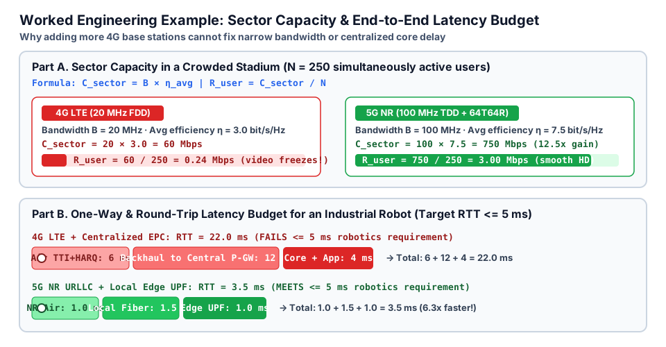
💡 Architectural Verdict:
- In the stadium, a
5×wider channel (100 MHzvs20 MHz) combined withMassive MIMO(2.5×spectral efficiency) multiplies total sector capacity by5 * 2.5 = 12.5×(750 Mbpsvs60 Mbps).- On the factory floor, even a
1.0 ms5G NRair interface will fail if packets still travel400 kmto a centralized gateway (1.0 + 12.0 + 4.0 = 17.0 ms > 5.0 ms). Meeting theURLLCtarget requires pairing5G NRshort slots with a localEdge UPFdeployed right on the factory premises (RTT = 3.5 ms).
What can go wrong and how to find it
When deploying early 5G networks, engineers frequently see the 5G icon on a phone while actual performance falls far short of IMT-2020 targets:
| Network Symptom | Root Engineering Cause | What to Check First |
|---|---|---|
5G cell throughput plateaus at 100–150 Mbps instead of gigabit speeds | The sector is running in a narrow 15–20 MHz low-band carrier (FDD n28 / n1) instead of 100 MHz TDD n78, or the subscriber profile still carries a legacy 4G UE-AMBR rate cap | Channel Bandwidth on the gNB base station and Subscribed UE-AMBR in the subscriber database |
Smartphone displays 5G, but RTT ping remains 25–35 ms just like 4G | The network operates in Non-Standalone 5G NSA (Option 3x) anchored to a legacy 4G EPC and a distant centralized P-GW, without URLLC short slots | Core architecture (NSA vs SA), physical location of the UPF / P-GW gateway, and the N3 transport route |
Stadium signal strength is excellent (RSRP = -75 dBm), but video uploads fail | Uplink congestion: the TDD frame allocates 80% of slots to Downlink, while thousands of fans simultaneously upload live video on the Uplink | TDD DL:UL slot pattern and UL PRB Utilization counters on the gNB |
An industrial sensor battery in a 5G network drains in a single week | Power-saving features (RRC_INACTIVE, eDRX, PSM) are disabled, or a full-power eMBB modem was installed instead of a low-power RedCap / NB-IoT module | Modem category and inactivity timer settings on the base station and core |
Data sessions drop on a high-speed train above 300 km/h | High Doppler frequency shift destroys subcarrier orthogonality at narrow 15 kHz spacing, or fast handover neighbor relations are missing | Configured Subcarrier Spacing SCS (30 kHz or 60 kHz resists Doppler shift much better) and handover thresholds |
⚠️ Common design pitfall: confusing peak data rate (
20 Gbps) with user experienced data rate (100 Mbps). The20 Gbpspeak occurs only in a lab when a single terminal in an empty cell claims400–800 MHzof spectrum with256-QAMmodulation and8MIMOlayers. For real capacity dimensioning, always use the average multi-user spectral efficiencyeta_avg!
Practice
- Predict without a calculator. If an operator widens a
5G NRsector from50 MHzto100 MHzusing the same antenna array and spectral efficiency, by what factor does the average speed per active user increase? - Calculate sector capacity. In a business district, a
5G NRbase station operates in an80 MHzchannel (B = 80 MHz) with an average spectral efficiency ofeta_avg = 6.5 bit/s/Hz. What is the total sector capacityC_sector, and what average throughput does each ofN = 130simultaneously active users receive? - Verify the latency budget. A factory controller requires
RTT <= 8 ms. The5G NRair interface takesT_air = 1.5 msandUPF+ application processing takesT_core = 1.5 ms, but theUPFgateway was left in a central data center600 kmaway (round-trip fiber delayT_transport = 9.0 ms). Does the system meet the8 msrequirement? What architectural change is required? - Classify by IMT-2020 pillars. Match three services to the vertices of the triangle (
eMBB,URLLC,mMTC): (a) live concert streaming from a 360-degree VR camera (80 Mbps); (b) automatic fault isolation on a high-voltage power grid within3 ms; (c) a city-wide network of500,000soil-moisture and pipe-leak sensors. - Starred engineering challenge ⭐. An operator wants to guarantee
N = 400simultaneously active fan-zone users an average speed of at leastR_user = 2.5 MbpsusingMassive MIMOwitheta_avg = 8.0 bit/s/Hz. What minimum channel bandwidthB(in MHz) does this sector need? Would a single4G LTE (20 MHz)carrier be enough?
Self-check
Question 1. Why can't an operator meet a RTT <= 5 ms industrial robotics requirement simply by swapping 4G eNodeB antennas for 5G gNB antennas while keeping a single centralized core gateway for the entire country?
Breakdown. Light travels through optical fiber at roughly 200,000 km/s (5 microseconds per kilometer, or about 1 ms per 100 km round-trip including optical repeaters and switches). If the user plane gateway sits several hundred kilometers from the factory, transport delay T_transport alone consumes 8–15 ms, blowing past the 5 ms budget even if radio latency were zero. That is why 5G pairs a <= 1 ms NR air interface with a local Edge UPF gateway deployed on or near the customer site.
Question 2. What is the fundamental conflict between eMBB and mMTC requirements for a radio modem?
Breakdown. An eMBB modem is built for maximum speed: it processes 100–400 MHz channels with 4 receive antennas (4Rx) and heavy digital signal processing, making it expensive and power-hungry. An mMTC modem sends only a few bytes per day: it does not need gigabits, but requires rock-bottom hardware cost, deep sleep states, and 10+ years of battery life at densities up to 1,000,000 devices per km².
Practice answers:
- It increases by exactly 2× (since
C_sector = B * eta_avgscales linearly with bandwidthB). C_sector = 80 * 6.5 = 520 Mbps; per-user average speedR_user = 520 / 130 = 4.0 Mbps.- Total latency is
RTT = 1.5 + 9.0 + 1.5 = 12.0 ms > 8.0 ms— the requirement fails due to long-haul transport. Deploying a localEdge UPFat the factory (or metroMECsite) cutsT_transportto1–2 msand solves the issue. - (a) 360° VR streaming —
eMBB; (b)3 mshigh-voltage grid protection —URLLC; (c)500,000city sensors —mMTC. - Required sector capacity:
C_sector = 400 * 2.5 = 1000 Mbps(1 Gbps). Minimum bandwidth:B = C_sector / eta_avg = 1000 / 8.0 = 125 MHz(e.g.,100 MHzinn78plus a25–40 MHzsecondary carrier). A single4G LTE (20 MHz)carrier falls short by more than6×.
Review and the criterion for moving on
Move on to the next lesson if you can, without looking at your notes:
- name the three limits of
4G LTEand explain their technical root causes; - spell out and define
IMT-2020,eMBB,URLLC, andmMTC; - state the core
IMT-2020targets:20 / 10 Gbpspeak rate,100 / 50 Mbpsuser rate,<= 1 ms(URLLC) and<= 4 ms(eMBB) air latency,1,000,000 dev/km²density, and500 km/hmobility; - calculate sector capacity
C_sector = B * eta_avgand end-to-end latencyRTT = T_air + T_transport + T_core.
Up next. In Lesson 2, we will dive into each of the three usage scenario pillars (eMBB, URLLC, and mMTC) and explore why their physical-layer parameters pull in opposite directions.
Standards and sources
- ITU-R Recommendation M.2083-0 (09/2015) — "IMT Vision — Framework and overall objectives of the future development of IMT for 2020 and beyond" (the foundational ITU document defining the
eMBB / URLLC / mMTCtriangle and the 8 capability parameters ofIMT-2020): itu.int. - ITU-R Report M.2410-0 (11/2017) — "Minimum requirements related to technical performance for IMT-2020 radio interface(s)" (exact numerical requirements for
20/10 Gbpspeak rate,1/4 mslatency,1-10^-5reliability, and10^6 dev/km²connection density). - 3GPP TR 38.913 (Release 15 / 16 / 17) — "Study on Scenarios and Requirements for Next Generation Access Technologies" (3GPP technical requirements for
5G NRand the5GSsystem).
