
In the previous course (gsm), we explored how second- and third-generation mobile networks work — from narrowband 2G GSM (TDMA $200\text{ kHz}$) voice channels and the first GPRS/EDGE packet overlay to the wideband code-division air interface of 3G UMTS (WCDMA $5\text{ MHz}$) and high-speed HSPA / HSPA+. By 2007–2008, it seemed that evolving 3G could satisfy mobile data demand for years to come. However, the mass adoption of touchscreen smartphones (iPhone and Android), video streaming, social media, and instant messengers with constant background push notifications triggered a tenfold explosion in packet traffic and exposed the fundamental architectural ceiling of 3G networks. In this opening lesson of the lte course, we examine why 3GPP launched the LTE (Long Term Evolution) project in specification TR 25.913, which four strict engineering targets defined 3GPP Release 8 — across peak data rate, user-plane and control-plane latency, spectrum flexibility, and cost per transferred megabyte — and why meeting those targets forced engineers to abolish both the Radio Network Controller (RNC) and the Circuit-Switched voice domain (CS Domain) for the first time in cellular history.
Goal and prerequisites
After this lesson, you will be able to:
- explain the four crises of 3G UMTS/HSPA networks in the smartphone era: exploding data volume with flat revenue (“traffic-vs-revenue scissors”), the Signaling Storm on RNC controllers caused by frequent small keep-alive packets from chat apps, high latency across the four-tier user plane (
NodeB → RNC → SGSN → GGSN), and WCDMA's rigid $5\text{ MHz}$ channel requirement; - state the target engineering metrics of 3GPP Release 8 LTE (TR 25.913): peak throughput of $\ge 100\text{ Mbit/s}$ in the downlink ($5\text{ bit/s/Hz}$ spectral efficiency) and $\ge 50\text{ Mbit/s}$ in the uplink ($2.5\text{ bit/s/Hz}$) within a $20\text{ MHz}$ channel, one-way radio access latency $< 5\text{ ms}$, and camp-to-active transition time $< 100\text{ ms}$;
- list the six standardized LTE channel bandwidths ($1.4$, $3$, $5$, $10$, $15$, and $20\text{ MHz}$) and justify why this scalability is essential for gradual 2G and 3G spectrum refarming;
- calculate the economic and technical gains of moving to a flat All-IP architecture (two user-plane node types instead of four, and complete removal of the parallel CS domain).
What you need to know in advance:
- the evolution of mobile generations 1G → 5G, frequency bands, and the difference between FDD and TDD duplexing from 2G/3G Mobile Networks (
gsm1, 3, 6); - the 2G/3G packet core architecture (SGSN, GGSN, GTP tunnels) and the 3G UMTS radio network (NodeB, RNC controller, WCDMA $5\text{ MHz}$ carrier, HSPA+) from 2G/3G Mobile Networks (
gsm70–79); - IP packet structure, throughput, RTT (Round-Trip Time) latency, and protocol overhead from IP Networks for Telecom Engineers (
ipnet1, 9, 17).
A real-life task
The year is 2009–2010. You are the Chief Technology Officer (CTO) of a national mobile operator. Over the past 18 months, the first 500,000 smartphone users have joined your 3G UMTS/HSPA network, and your marketing team has introduced flat-rate monthly unlimited data plans. At the morning operations review, three urgent reports land on your desk:
- Given (operational and financial baseline of the 3G network):
- Traffic explosion vs. flat revenue: packet data volume has grown $12\times$, while subscribers pay a fixed monthly fee. To stay profitable, the carrier must cut the delivery cost of $1\text{ MB}$ by at least $4\text{–}5\times$.
- RNC processor overload (“Signaling Storm”): even when the HSPA air interface bandwidth is only $35\%$ utilized by user data, the central processors of your RNC controllers hit $95\text{–}100\%\text{ CPU}$! The culprit: smartphone messengers and email clients send tiny
keep-alivepackets ($60\text{ bytes}$) every $30\text{–}60\text{ seconds}$. To transmit those $60\text{ bytes}$, the 3G network repeatedly promotes the handset from battery-saving sleep to a dedicated radio channel and back, exchanging more than $20\text{–}25$ signaling messages across the UE, NodeB, RNC, and SGSN and spending nearly $2\text{ seconds}$ just waking up the connection. - Spectrum refarming deadlock: in the rural $900\text{ MHz}$ band, you have only $3\text{ MHz}$ of free contiguous spectrum, whereas 3G WCDMA physically requires an unbroken $5\text{ MHz}$ block ($3.84\text{ Mcps}$) — deploying 3G there is impossible!
You must decide whether to keep buying expensive 3G RNC cabinets and SGSN/GGSN gateways or launch a fourth-generation LTE (3GPP Release 8) network whose radio access and core architecture are redesigned from the ground up.
Why 3G UMTS/HSPA networks hit an architectural ceiling
When 3G UMTS (Release 99) was designed in the late 1990s, circuit-switched voice (CS) was still the primary revenue source, and mobile data was envisioned as occasional web browsing or file downloads from a laptop. Consequently, 3G inherited four fundamental limitations that became critical bottlenecks in the era of always-on smartphones and interactive IP applications:
- Two parallel core networks (
CS Domain+PS Domain): operators had to purchase, power, cool, and maintain two separate equipment chains — a voice core (MSC Server + MGW, running SS7 / SIGTRAN / BICC / H.248) and a packet core (SGSN + GGSN, running GTPv1 tunnels). - Four user-plane nodes on every packet path and the RNC bottleneck: in 3G, every subscriber IP packet traversed four network elements in series: Base Station (
NodeB) $\rightarrow$ Radio Network Controller (RNC) $\rightarrow$ Serving Node (SGSN) $\rightarrow$ Gateway Node (GGSN). The centralized RNC handled air-interface ciphering, RLC packet reassembly, Soft Handover combining, and radio resource management for hundreds of base stations simultaneously. Every surge in smartphone adoption turned the RNC into the most expensive and congested choke point in the network. - Complex radio state machine and high latency (RTT $50\text{–}150\text{ ms}$): to save battery in WCDMA, the RNC constantly moved handsets across four states (
IDLE,CELL_PCH,CELL_FACH,CELL_DCH). Promoting a handset from idle/sleep to a high-speed dedicated channel took $1.0\text{–}2.5\text{ seconds}$, and round-trip packet latency (ping / RTT) remained $40\text{–}100\text{ ms}$ even with HSPA — too slow for cloud gaming, real-time control, and snappy web rendering. - Rigid $5\text{ MHz}$ channel bandwidth and WCDMA code limits: because WCDMA's chip rate is fixed at $3.84\text{ Mcps}$, a single 3G carrier cannot fit into a narrow $1.4\text{–}3\text{ MHz}$ refarmed slice, nor can it scale into a single wide $15\text{–}20\text{ MHz}$ pipe without bonding multiple carriers. Moreover, at very high data rates in a wideband $5\text{ MHz}$ channel, multipath reflections destroy the orthogonality of OVSF spreading codes.
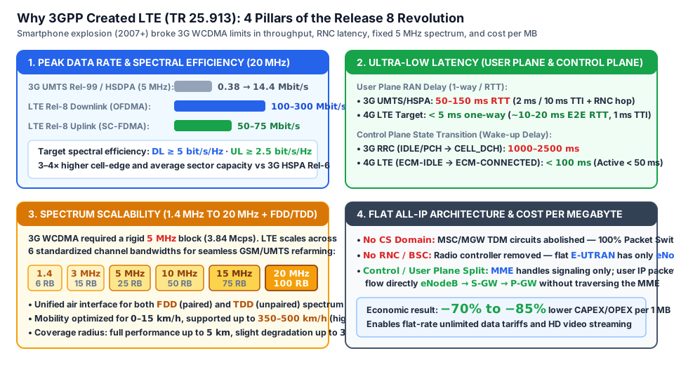
3GPP design targets for LTE (TR 25.913 and TS 36.300)
In late 2004, at a workshop in Toronto, 3GPP initiated the Long Term Evolution work item for the radio access network alongside SAE (System Architecture Evolution) for the packet core. Technical Report 3GPP TR 25.913 established four strict engineering targets for Release 8 (frozen in December 2008, with the first commercial networks launched in December 2009 in Stockholm and Oslo):
1. A 3–4× leap in peak data rates and spectral efficiency
Within a reference $20\text{ MHz}$ channel bandwidth, the LTE air interface was required to deliver:
- Downlink (base station to handset): a peak data rate of at least $100\text{ Mbit/s}$ (reaching $150\text{ Mbit/s}$ in practice with $2\times 2\text{ MIMO}$, and $300\text{ Mbit/s}$ with $4\times 4\text{ MIMO}$). This corresponds to a peak spectral efficiency of $\ge 5.0\text{ bit/s/Hz}$ ($100\text{ Mbit/s} / 20\text{ MHz} = 5\text{ bit/s/Hz}$).
- Uplink (handset to base station): a peak data rate of at least $50\text{ Mbit/s}$ (up to $75\text{ Mbit/s}$ with 64-QAM), corresponding to a peak spectral efficiency of $\ge 2.5\text{ bit/s/Hz}$ ($50\text{ Mbit/s} / 20\text{ MHz} = 2.5\text{ bit/s/Hz}$).
- Average sector capacity and cell-edge throughput: $3\text{–}4\times$ higher in the downlink and $2\text{–}3\times$ higher in the uplink compared to baseline 3G HSPA (Release 6).
2. Drastic latency reduction (User Plane and Control Plane)
LTE strictly separated and specified two distinct latency budgets:
- User Plane Latency: one-way transit time of an IP packet across the radio access network (between the UE and the RAN edge node in an unloaded cell) must be under $5\text{ ms}$! To achieve this, the minimum TTI (Transmission Time Interval) — which was $10\text{–}20\text{ ms}$ in 3G Rel-99 and $2\text{ ms}$ in HSPA — was shortened to $1\text{ ms}$ in LTE. In live networks, this yields an end-to-end ping (E2E RTT) of $10\text{–}20\text{ ms}$, rivaling wired broadband!
- Control Plane Latency: transitioning a handset from battery-saving camp state (
IDLE) to active data transfer (ACTIVE / CONNECTED) must take less than $100\text{ ms}$ (and waking from dormant state within connected mode less than $50\text{ ms}$), while supporting at least $200$ active users per $5\text{ MHz}$ cell (and up to $400$ in wider bandwidths).
3. Spectrum flexibility (1.4 to 20 MHz + unified FDD/TDD)
Unlike 3G WCDMA's fixed $5\text{ MHz}$ carrier, LTE's orthogonal subcarrier air interface (OFDMA / SC-FDMA) scales smoothly across six standardized channel bandwidths:
- $1.4\text{ MHz}$ (allows launching LTE in a tiny spectrum slice by freeing just $7$ GSM carriers of $200\text{ kHz}$ each!);
- $3\text{ MHz}$ (ideal for incremental refarming of $900$ and $1800\text{ MHz}$ bands);
- $5\text{ MHz}$ (a direct one-to-one drop-in replacement for a single 3G UMTS carrier);
- $10\text{ MHz}$, $15\text{ MHz}$, and $20\text{ MHz}$ (high-capacity 4G broadband pipes).
- Furthermore, a single unified LTE standard supports both Frequency Division Duplex (FDD — paired spectrum) and Time Division Duplex (TDD — unpaired spectrum).
4. Flat All-IP architecture and lower cost per megabyte
To slash delivery costs and eliminate latency hops, LTE and the EPC (Evolved Packet Core) introduced three architectural breakthroughs:
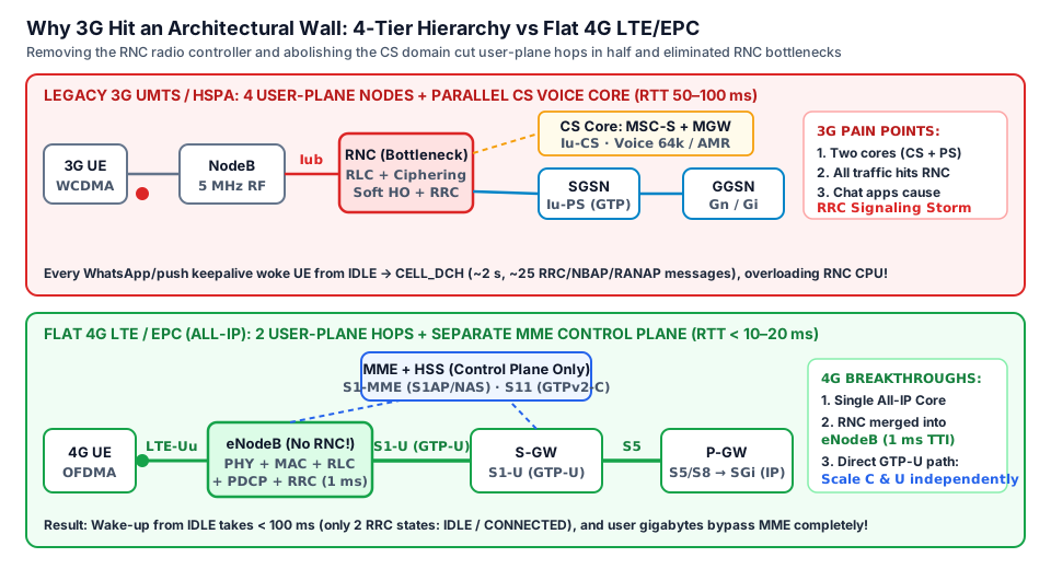
- Complete abolition of the Circuit-Switched domain (
CS Domain): LTE has no MSC switches, no MGW media gateways, and no $64\text{ kbit/s}$ TDM circuits. The entire network is 100% Packet-Switched (All-IP PS Only) — web pages, video, and voice (VoLTE) all travel as IP packets. - Elimination of the Radio Network Controller (
RNC/BSC) — flat RAN: all radio resource management, encryption, and $1\text{ ms}$ packet scheduling move directly into the fourth-generation base station — the eNodeB (Evolved NodeB). - Control Plane / User Plane separation in the core: the signaling mobility node (MME) is completely removed from the user data path! Heavy gigabytes of video flow directly from the eNodeB through packet gateways (S-GW $\rightarrow$ P-GW) to the Internet — traversing only two node types instead of four in 3G (
NodeB → RNC → SGSN → GGSN).
Worked example: engineering and financial math of 3G HSPA → 4G LTE migration
Let's return to the CTO challenge from the beginning of the lesson and verify with exact numbers how migrating from 3G HSPA to 4G LTE solves all three operator pain points (throughput/capacity, RNC signaling storms, and cost per megabyte):
# Spectral efficiency and peak throughput comparison: 3G HSPA vs 4G LTE (Release 8)
spectral_and_throughput_comparison:
  legacy_3g_hspa_rel6:
    channel_bandwidth_mhz: 5.0
    dl_peak_rate_mbps: 14.4
    ul_peak_rate_mbps: 5.76
    dl_spectral_efficiency_bps_per_hz: 2.88   # 14.4 Mbit/s / 5 MHz = 2.88 bit/s/Hz
  lte_rel8_target_tr25913:
    channel_bandwidth_mhz: 20.0
    dl_target_rate_mbps: 100.0                # 150 Mbit/s for 2x2 MIMO (300 Mbit/s for 4x4 MIMO)
    ul_target_rate_mbps: 50.0                 # up to 75 Mbit/s with 64-QAM
    dl_spectral_efficiency_bps_per_hz: 5.0    # 100 Mbit/s / 20 MHz = 5.0 bit/s/Hz
    ul_spectral_efficiency_bps_per_hz: 2.5    # 50 Mbit/s / 20 MHz = 2.5 bit/s/Hz
Now let's compare packet latency, handset wake-up time, and user-plane hops between the 4-tier 3G hierarchy and the flat 4G LTE architecture:
# Latency and transit node hierarchy audit (User Plane & Control Plane)
latency_and_hierarchy_audit:
  3g_umts_hspa_4_nodes:
    user_plane_path: "NodeB -> RNC -> SGSN -> GGSN (4 nodes)"
    transmission_time_interval_tti_ms: 2.0
    user_plane_ran_one_way_ms: 25.0
    end_to_end_ping_rtt_ms: 65.0
    idle_to_active_wakeup_ms: 1800.0          # 1.8 s (IDLE -> CELL_DCH via RNC)
  4g_lte_epc_flat_2_tiers:
    user_plane_path: "eNodeB -> S-GW/P-GW (2 node types, no RNC, bypassing MME)"
    transmission_time_interval_tti_ms: 1.0
    user_plane_ran_one_way_target_ms: 5.0     # < 5 ms per TR 25.913
    end_to_end_ping_rtt_ms: 15.0              # 10..20 ms in production networks
    idle_to_active_wakeup_target_ms: 100.0    # < 100 ms (only 2 states: IDLE and CONNECTED)
Let's summarize all 3GPP TR 25.913 (LTE Release 8) target metrics alongside 3G UMTS / HSPA in a single reference table:
| Engineering Parameter | 3G UMTS (Rel-99) | 3.5G HSPA (Rel-6/7) | 4G LTE Target (3GPP TR 25.913 / Rel-8) | Engineering Benefit for the Operator |
|---|---|---|---|---|
| Single Channel Bandwidth | Fixed 5 MHz | Fixed 5 MHz (or $2\times 5\text{ MHz}$) | Flexible: 1.4 / 3 / 5 / 10 / 15 / 20 MHz | Refarm any narrow 2G/3G spectrum slice |
| Peak Downlink Rate | 384 kbit/s – 2 Mbit/s | 14.4 – 21 Mbit/s | $\ge 100\text{ Mbit/s}$ (150 Mbit/s w/ $2\times 2\text{ MIMO}$, 300 Mbit/s w/ $4\times 4$) | Buffer-free HD video and fast web loading |
| Peak Uplink Rate | 64 – 384 kbit/s | 5.76 – 11.5 Mbit/s | $\ge 50\text{ Mbit/s}$ (up to 75 Mbit/s w/ 64-QAM) | Fast video uploads, cloud backups, and live streams |
| Peak Spectral Efficiency | 0.08 – 0.4 bit/s/Hz | 2.88 bit/s/Hz (DL) | $\ge 5.0\text{ bit/s/Hz}$ (DL) & $\ge 2.5\text{ bit/s/Hz}$ (UL) | More megabits from every MHz of expensive spectrum |
| Minimum Scheduling TTI | 10 / 20 / 40 / 80 ms | 2 ms (HSDPA) | 1 ms (1 subframe = 2 slots of $0.5\text{ ms}$) | Sub-millisecond scheduler adaptation to fading |
| RAN User Plane Delay (1-way) | 70 – 150 ms | 20 – 40 ms | $< 5\text{ ms}$ (end-to-end ping RTT 10–20 ms) | Fiber-like responsiveness over the air |
IDLE → ACTIVE Wake-up Time | 2000 – 3000 ms | 1000 – 2000 ms | $< 100\text{ ms}$ (from dormant DRX $< 50\text{ ms}$) | Eliminates handset lag when tapping a link |
| User Plane Node Chain | 4 nodes (NodeB→RNC→SGSN→GGSN) | 4 nodes (through RNC) | Flat: eNodeB → S-GW → P-GW (no RNC, bypasses MME) | $70\text{–}85\%$ reduction in cost per $1\text{ MB}$ |
| Core Switching Domains | Dual: CS + PS | Dual: CS + PS | All-IP PS only (CS domain abolished) | Eliminates maintaining a second (voice) core network |
| Mobility Speed Support | Up to 120–250 km/h | Up to 250 km/h | Optimal 0–15 km/h, high performance to 120 km/h, up to 350–500 km/h | Reliable connectivity in cars and high-speed trains |
💡 Architectural verdict (decision for the CTO from the lesson task): Scaling a legacy 3G hierarchy by purchasing more RNC controllers during a smartphone traffic boom is economic suicide. Migrating to 4G LTE (3GPP Release 8) solves all three problems at the root: (1) abolishing the RNC node and simplifying the radio state machine to two states with $< 100\text{ ms}$ wake-up latency completely eliminates the radio controller bottleneck; (2) flexible $1.4\text{ and }3\text{ MHz}$ channel bandwidths immediately unlock the free $3\text{ MHz}$ block in the $900\text{ MHz}$ band where a $5\text{ MHz}$ WCDMA carrier could never fit; (3) the flat All-IP architecture without a CS domain and with user traffic bypassing the MME cuts CAPEX and OPEX per transferred megabyte by more than $4\text{–}5\times$.
# Operator unit economics model (OPEX/CAPEX per 1 GB of traffic): 3G vs 4G LTE
operator_unit_economics_model:
  narrow_spectrum_900mhz_3mhz_block:
    wcdma_3g_deployment: "Impossible (requires at least 5.0 MHz of contiguous spectrum)"
    lte_4g_deployment: "Supported: standard 3.0 MHz LTE channel (15 Resource Blocks)"
  cost_and_signaling_efficiency:
    relative_cost_per_mb_3g_hspa: 1.00        # Baseline (100% cost across NodeB+RNC+SGSN+GGSN)
    relative_cost_per_mb_4g_lte: 0.22         # 22% (-78% cost thanks to flat network without RNC/CS)
    capacity_gain_per_mhz_factor: 3.5         # 3.5x more traffic carried per MHz of spectrum
What can go wrong and how to find it
When planning 2G/3G-to-LTE migrations and evaluating live network performance, engineers frequently encounter three classic design and troubleshooting pitfalls:
| Network or Project Symptom | Possible Cause | What the Engineer Should Check |
|---|---|---|
| Marketing advertises “LTE up to $150\text{ Mbit/s}$”, but even at night right next to the tower a smartphone reaches at most $36\text{–}37\text{ Mbit/s}$ | The eNodeB sector is configured with a narrow $5\text{ MHz}$ channel bandwidth (e.g., after refarming a single 3G UMTS carrier) instead of the maximum $20\text{ MHz}$ bandwidth | Check the configured channel bandwidth on the eNodeB sector: LTE peak rate scales linearly with bandwidth ($5\text{ MHz}$ provides one-fourth the ceiling of $20\text{ MHz}$, or roughly $37.5\text{ Mbit/s}$ with $2\times 2\text{ MIMO}$). |
| Data ping (RTT) on 4G LTE is a snappy $15\text{ ms}$, yet pressing the dial button causes a $2.5\text{–}4\text{ second}$ delay before the first ringback tone | Packet voice (VoLTE) is not enabled on the network or handset, and because LTE has no CS domain, every voice call forces the phone to fall back to 2G/3G (CSFB) | Inspect signaling traces to verify whether the call triggers CSFB (Circuit Switched Fallback) to 2G/3G due to the absence of a circuit-switched CS domain in the All-IP LTE/EPC core. |
| After refarming $2100\text{ MHz}$ from 3G to LTE, core signaling CPUs experience a spike in messages on every background smartphone keep-alive packet | Handsets are released from active mode to idle sleep (IDLE) too aggressively due to an overly short UE Inactivity Timer (e.g., $2\text{–}3\text{ s}$ instead of $10\text{ s}$) on the eNodeB | Audit the UE Inactivity Timer and discontinuous reception settings on the eNodeB so background messenger packets do not repeatedly tear down and recreate core signaling connections. |
⚠️ Common beginner mistake: assuming that LTE's headline speed of $100\text{–}150\text{ Mbit/s}$ is automatically available on every 4G tower regardless of spectrum holdings. Remember: the 3GPP TR 25.913 targets ($\ge 100\text{ Mbit/s}$ downlink and $\ge 50\text{ Mbit/s}$ uplink) are defined for the maximum $20\text{ MHz}$ channel bandwidth according to $R = \eta \cdot \Delta F$. If an operator holds only $5\text{ MHz}$ or $10\text{ MHz}$ in a given band, the sector's peak throughput scales down by a factor of $4$ or $2$, respectively!
Practice
Complete these five progressive exercises (from predicting outcomes to the starred independent calculation):
- Predict the outcome: An operator clears a contiguous $2.4\text{ MHz}$ block in the $1800\text{ MHz}$ band (by freeing $12$ GSM carriers of $200\text{ kHz}$ each). Can they deploy a single 3G UMTS (WCDMA) carrier in this block? What is the widest standardized 4G LTE channel bandwidth (out of $1.4$, $3$, $5$, $10$, $15$, and $20\text{ MHz}$) that will fit inside this $2.4\text{ MHz}$ block?
- Verify with the spectral efficiency formula: According to 3GPP TR 25.913, the target peak spectral efficiency of LTE Release 8 is $5.0\text{ bit/s/Hz}$ in the downlink and $2.5\text{ bit/s/Hz}$ in the uplink. Calculate the target peak downlink and uplink data rates when an operator deploys LTE in a $10\text{ MHz}$ channel.
- Explain the architectural decision: Why did 3GPP engineers completely abolish the dedicated Radio Network Controller (RNC) in 4G LTE, moving its functions into the eNodeB base station, and how did this simultaneously improve User Plane latency and
IDLE → ACTIVEwake-up time? - Modify the input parameters: Suppose that in a 3G HSPA network with an RNC, one-way radio access delay is $25\text{ ms}$, and the packet core plus transport to the server add another $10\text{ ms}$ one-way (for an end-to-end $\text{RTT} = 2 \times (25 + 10) = 70\text{ ms}$). What will the end-to-end RTT become after migrating to 4G LTE if one-way radio access delay drops to the 3GPP TR 25.913 target ($4.5\text{ ms}$) and the flat EPC core plus transport take $5.5\text{ ms}$ one-way?
- Do it yourself ⭐: An operator holds $15\text{ MHz}$ in the $2100\text{ MHz}$ band currently occupied by three $5\text{ MHz}$ 3G HSPA carriers with an average sector spectral efficiency of $1.2\text{ bit/s/Hz}$ (total average sector throughput $15\text{ MHz} \times 1.2 = 18\text{ Mbit/s}$). Refarming all $15\text{ MHz}$ into a single wideband 4G LTE ($15\text{ MHz}$) carrier triples average spectral efficiency to $3.6\text{ bit/s/Hz}$, while peak spectral efficiency reaches $7.5\text{ bit/s/Hz}$ (with $2\times 2\text{ MIMO}$). Calculate the new average and peak throughput of the $15\text{ MHz}$ LTE sector, and determine how many full gigabytes of data this sector delivers during a busy hour ($3600\text{ seconds}$) at $100\%$ average load (using $1\text{ byte} = 8\text{ bits}$ and $1\text{ GB} = 1000\text{ MB}$).
Self-check
Test yourself with two review questions and detailed explanations, then check your answers to the practice tasks:
Question 1. Why did smartphones running chat apps overload RNC controller CPUs (“Signaling Storm”) in 3G UMTS networks even when total transferred megabytes were modest, and how does the 4G LTE architecture eliminate this issue?
- Answer walkthrough: To conserve battery in 3G UMTS/HSPA, the centralized RNC managed a four-state radio machine (
IDLE,CELL_PCH,CELL_FACH,CELL_DCH). Every tiny backgroundkeep-alivepacket forced the RNC to execute a lengthy channel promotion and teardown cycle ($\sim 1.5\text{–}2.5\text{ s}$ and over $20$ signaling messages across UE, NodeB, RNC, and SGSN). In 4G LTE, the RNC is abolished completely, the $1\text{ ms}$ scheduler lives inside the eNodeB, and transitions between idle and connected states complete in $< 100\text{ ms}$ without any intermediate radio controller.
Question 2. What does it mean that “4G LTE / EPC completely abolished the Circuit-Switched (CS) domain”, and what are the two main consequences for a mobile operator?
- Answer walkthrough: Unlike 2G GSM and 3G UMTS — which ran two parallel cores, a telephone CS domain (
MSC/VLR,MGW) for voice and a packet PS domain (SGSN,GGSN) for data — the 4G architecture retains only the All-IP packet core (EPC). First consequence (economic): the operator no longer builds or maintains two parallel switching and transport networks. Second consequence (technical): LTE cannot open a classic $64\text{ kbit/s}$ voice circuit — to make a phone call, a handset must either send voice as prioritized IP packets through the multimedia subsystem (VoLTE) or fall back to 2G/3G radio for the duration of the call (CSFB).
Answers to practice
- Answer to Task 1: You cannot deploy 3G UMTS (WCDMA) in a $2.4\text{ MHz}$ block because a single WCDMA carrier strictly requires $5.0\text{ MHz}$. In 4G LTE, a $2.4\text{ MHz}$ block accommodates the standardized $1.4\text{ MHz}$ channel bandwidth (the next step up, $3.0\text{ MHz}$, exceeds $2.4\text{ MHz}$).
- Answer to Task 2: For a $\Delta F = 10\text{ MHz}$ channel, the target peak downlink rate is $10\text{ MHz} \times 5.0\text{ bit/s/Hz} = \mathbf{50\text{ Mbit/s}}$ (up to $75\text{ Mbit/s}$ in practice with $2\times 2\text{ MIMO}$), and the target peak uplink rate is $10\text{ MHz} \times 2.5\text{ bit/s/Hz} = \mathbf{25\text{ Mbit/s}}$.
- Answer to Task 3: Removing the intermediate RNC eliminated an extra transit node and the
Iubbackhaul hop from every packet's path. Because the packet scheduler and radio control protocol moved directly into the eNodeB with a $1\text{ ms}$ subframe interval, one-way radio delay dropped to $< 5\text{ ms}$ and camp-to-active transition time dropped to $< 100\text{ ms}$. - Answer to Task 4: One-way delay in 4G LTE is $4.5\text{ ms} + 5.5\text{ ms} = 10.0\text{ ms}$. The end-to-end round-trip time is $\text{RTT} = 2 \times 10.0\text{ ms} = \mathbf{20\text{ ms}}$ (a $3.5\times$ reduction compared to $70\text{ ms}$ in 3G!).
- Answer to Task 5 ⭐:
* New average LTE ($15\text{ MHz}$) sector throughput: $15\text{ MHz} \times 3.6\text{ bit/s/Hz} = \mathbf{54\text{ Mbit/s}}$ (vs. $18\text{ Mbit/s}$ in 3G).
* New peak LTE ($15\text{ MHz}$) sector throughput: $15\text{ MHz} \times 7.5\text{ bit/s/Hz} = \mathbf{112.5\text{ Mbit/s}}$.
* Total data volume in $1\text{ hour}$ ($3600\text{ s}$) at $54\text{ Mbit/s}$ ($54 / 8 = 6.75\text{ MB/s}$): $6.75\text{ MB/s} \times 3600\text{ s} = 24,300\text{ MB} = \mathbf{24.3\text{ GB}}$ per hour from a single sector!
Review and the criterion for moving on
- Quick review from the
gsmcourse: recall which two nodes formed the 2.5G/3G PS Core (SGSNandGGSN) and which tunneling protocol (GTP) connected them — in just three lessons we will see how they evolved into the 4G EPC core. - Criterion for moving on: you are ready for the next lesson if you can name from memory all six standardized LTE channel bandwidths ($1.4 \dots 20\text{ MHz}$), the 3GPP TR 25.913 targets ($\ge 100 / 50\text{ Mbit/s}$ in $20\text{ MHz}$, $< 5\text{ ms}$ User Plane, $< 100\text{ ms}$ Control Plane), and the three main architectural differences between flat 4G and hierarchical 3G.
Next, in Lesson 2 (lte-vs-4g), we will unravel the “4G” naming paradox: why commercial LTE Release 8 initially fell short of the strict ITU-R IMT-Advanced ($1\text{ Gbit/s}$) benchmark, and how LTE-Advanced (Rel-10) and LTE-Advanced Pro (Rel-13+) conquered that summit.
Standards and sources
- 3GPP TR 25.913 — Requirements for Evolved UTRA (E-UTRA) and Evolved UTRAN (E-UTRAN) (the foundational specification defining the $100/50\text{ Mbit/s}$ throughput targets, $< 5\text{ ms}$ / $< 100\text{ ms}$ latency budgets, and $1.4\text{–}20\text{ MHz}$ spectrum flexibility).
- 3GPP TS 36.300 — Evolved Universal Terrestrial Radio Access (E-UTRA) and Evolved Universal Terrestrial Radio Access Network (E-UTRAN); Overall description; Stage 2 (overall description of the flat LTE radio network and $1\text{ ms}$ subframe scheduling).
- 3GPP TS 23.401 — General Packet Radio Service (GPRS) enhancements for Evolved Universal Terrestrial Radio Access Network (E-UTRAN) access (architecture of the All-IP EPC core without a circuit-switched CS domain).
